The Use of Magnet for motor rotor in Electric Motors
Electric motors power electric autos and assembly line robots. In many high-performance designs, the Magnet for motor rotor is essential. Long-lasting neodymium, samarium cobalt, or ferrite magnets create a continuous magnetic field that operates on the stator windings to generate force. Standard wound rotors need brushes and slide rings. Permanent magnet rotors don't. This simplifies and saves energy. Buying managers, R&D engineers, and quality assurance teams must understand how these magnets function, perform, and fit into motor systems to compete in industrial markets. Because efficiency requirements like IE4 and IE5 are tightening.
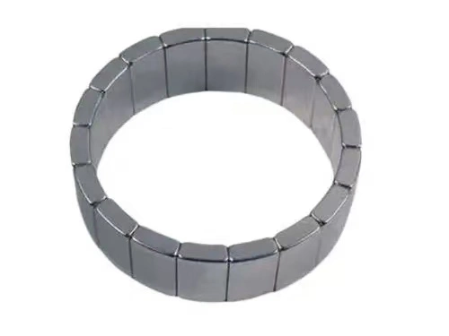
Understanding the Role of Magnets in Motor Rotors
How Permanent Magnets Generate Torque
Magnets in the Magnet for motor rotor's midsection provide a continuous magnetic field that responds with the stator's changing magnetic field. Electromagnetic fields rotate as power travels through stator coils. The rotor's permanent magnets are pushed and pulled by this field, creating spinning power. Magnet for motor rotor strength and location affects motor power and speed. Tesla's (T) magnetic flux density is crucial for engineers constructing electric automobile traction motors or robot servo motors. High-quality neodymium magnets have remanence values between 1.1T and 1.48T, allowing designers to construct smaller motors without reducing power.
Permanent Magnets vs. Electromagnetic Rotors
Electronic rotors are employed in classical induction motors. When electricity runs through rotor windings, a magnetic field is created. These designs are sturdy and inexpensive, but rotor wire resistive losses reduce performance. Permanent Magnet for motor rotors eliminate copper losses, increasing efficiency by 3–7%. For routinely operating machinery like HVAC compressors or industrial pumps, even tiny efficiency gains add up to large savings each year. Even though permanent magnet choices cost more initially, buying teams prefer them for long-term operational expenses.
Magnetic Interplay Between Rotor and Stator
The interaction between Magnet for motor rotors and stator windings determines motor properties, including cogging torque, back EMF, and torque ripple. Cogging torque is the magnetic resistance when something rotates without current. Medical and precision robots are especially susceptible to noise and vibration. Advanced rotor designs fix this via magnet skewing or segmentation, which spreads magnetic force over the rotor's diameter. Quality assurance managers can set the correct acceptance requirements for OEM components by knowing this design information.
Design Principles of Magnet-Based Motor Rotors
Optimizing Magnetic Flux Paths
When constructing an efficient motor, watch how magnetic flux travels between the rotor and stator. Engineers study magnetic flux flow using finite element analysis (FEA) to detect weak or strong spots. Magnet for motor rotor flux path performance depends on arc radius, width, and pole count. Our standard motor rotor magnets feature an outside arc radius of R36 (+0.2 / -0.1) mm and an inner arc radius of R28.3 (+0.3 / 0). After extensive testing, these sizes were chosen for magnetic and mechanical performance. These strict specifications ensure air gap diameters are always the same, minimizing performance variances between production runs.
Material Selection for Durability and Performance
Besides the magnet, the rotor has stacked steel plates that guide magnetic flux and avoid eddy current losses. Silicon steel laminations 0.35–0.5 mm thick prevent energy loss at high frequencies. The ideal balance of magnetic strength and weight is our 7.6 (+0 / -0.2) mm Magnet for motor rotor thickness. Centrifugal forces are significant in high-speed applications. Material selection also considers working temperature. An automobile traction motor's rotor may grow hotter than 150°C, hence it needs magnets with a high intrinsic coercivity (Hcj >25kOe) to maintain magnetism.
Mechanical Design for High-Speed Operation
EV power systems and industrial motors go beyond 10,000 RPM, stressing the Magnet for motor rotors. For low-speed usage, sticky glue can hold items. Carbon fiber sleeves or stainless steel retention cans are employed for high-speed conditions. Our Magnet for motor rotor's axial length (62 ±1 mm) and breadth (50 (+0 / -1) mm) cater to various installation scenarios while maintaining balance. Purchasing managers should verify magnetic requirements, engineering model mechanical retention techniques, and process certifications while comparing providers.
Performance Optimization and Maintenance of Magnet Motor Rotors
Routine Inspection and Diagnostic Practices
Care for permanent magnet motors differs from that of induction motors. Gaussmeters or Hall effect monitors should be used for frequent Magnet for motor rotor flux strength assessments since thermal stress, mechanical strain, and corrosion can damage magnets. Vibration analysis can detect loose or unbalanced magnets before they fail. Production managers should standardize motor-driven equipment performance parameters, including current draw, temperature increase, and noise signature. This lets them spot rotor issues early. Strategic procedures reduce unexpected downtime and extend equipment service life, which affects the total cost of ownership.
Addressing Common Magnet-Related Failures
Permanent magnet demagnetization, produced by too much heat or conflicting magnetic fields, is the worst failure. Reduced power output, increased current consumption, and unstable speed control are symptoms. R&D engineers should check Magnet for motor rotor operating temperature grades against application thermal profiles. SH grades (150°C) are suitable for industrial applications, whereas UH grades (180°C) are best for automobiles. Ni-Cu-Ni stacking prevents corrosion in moist or chemically adverse conditions. This is crucial for agricultural and seafaring gear.
Cooling Strategies for Extended Lifespan
The motor's Magnet for motor rotor characteristics is maintained by temperature control. Forced air circulation, heat sink integration, or liquid cooling layers can maintain rotor temperatures. Some contemporary models include rotor assemblies with cooling channels. For continuous-duty applications like HVAC systems or industrial conveyors, operations managers should engage with suppliers to validate thermal modeling for motor thermal design. Our production location can do custom thermal testing to fulfill duty cycle criteria.
Comparing Magnet-Based Rotor Technologies for Industrial Applications
Permanent Magnet vs. Squirrel Cage Rotors
Because they are strong and affordable, squirrel cage induction motors are used in industry. However, permanent magnet synchronous motors (PMSM) are advantageous for size, controllability, and efficiency. PMSMs' better power density makes designs smaller and lighter, which is significant for airplanes, robotics, and mobile equipment. Efficiency is especially evident when employing VFDs for variable-speed applications. Partial load induction motors lose more power. Procurement directors should undertake a total cost of ownership assessment that incorporates energy costs when comparing the cost of capital to the cost of running an asset throughout its lifetime.
Neodymium vs. Ferrite Rotor Magnets
Motor performance and cost depend on material choice. NdFeB magnets have a high energy density (BHmax values can reach 52 MGOe), allowing engineers to construct tiny, powerful Magnet for motor rotors. Ferrite magnets lose performance (BHmax = 5 MGOe) but are cheaper and more stable at high temperatures. Electric bicycle motors, generator blades, and cheap industrial fans employ ferrites. However, high-performance servo systems and EV traction motors require neodymium magnets. Our OEM customisation services deal with both types of materials and provide technical guidance to ensure the magnet shape matches each material's magnetic properties.
Surface-Mounted vs. Interior Permanent Magnet Designs
Design impacts efficiency, cost, and complexity of rotor production. Surface-mounted Magnet for motor rotors link magnets to the exterior, making assembly easier but requiring strong magnet retention. Interior permanent magnet (IPM) rotors feature magnets in their cores. This mechanically shields magnets and allows for resistant torque. SPM designs are easier to build and modify, whereas IPM designs are excellent for high-speed activities and EV traction field-weakening procedures. Quality assurance teams should pick rotors depending on application needs. Customize acceptance testing to assess design-specific features like magnet position accuracy and hold.
Procurement Guide: Buying Magnet Motor Rotors for B2B Clients
Evaluating Supplier Capabilities and Certifications
When buying permanent Magnet for motor rotor components, examine vendors' technical and quality credentials. IATF 16949 certification demonstrates that a business meets tight car industry manufacturing norms, which Tier 1 and Tier 2 suppliers value. ISO 9000 accreditation assures a baseline quality system. Patent portfolios demonstrate engineers' innovation, while concept patents demonstrate firms' ability to tackle complicated challenges for customizing projects. Besides ISO 9000 and IATF 16949 certifications, our facility has three concept patents and six utility model patents for magnet retention and performance. These credentials provide procurement managers with confidence in IP execution and defense.
Customization Options and Technical Support
Standard catalog criteria are seldom satisfied by industrial motor usage. Good OEM/ODM providers allow clients to utilize their own designs or samples for bespoke sizes, tolerances, and performance grades. The magnet for motor rotor angle is vital for customization. Our 90° ±2° arrangement is suitable for various applications, but we can provide custom geometries for other rotor designs. Post-processing services should include selecting the surface layer (nickel, zinc, epoxy) and magnetization orientation (radial, axial, multipole). R&D engineers benefit from technical cooperation, such as FEA simulation and prototype iteration. Our technical staff consults with clients to optimize rotor magnetic circuits before they make production equipment.
Logistics and Lead Time Considerations
Global procurement requires reliable delivery strategies and flexible shipping options. Your design can be tested in 10–15 days with standard sample wait periods. Large orders take 35–40 days to deliver, allowing you to plan production without overspending on inventories. Shock- and moisture-proof packaging protects the Magnet for motor rotors during international delivery. Shipments can be sent by sea for big quantities, air for quick refilling, or DHL, FedEx, UPS for samples and small volumes. Supply chain managers should establish clear communication protocols for order tracking, customs documentation, and quality hold processes to reduce production disruptions.
Quality Assurance and After-Sales Support
Full quality inspections reduce the cost of output delays. Third-party tests like RoHS compliance and SGS inspection for dimensions and magnetic property verification provide independent assurance. Suppliers who offer one-year quality guarantees and return/replacement programs care about their consumers. Batch tracking links final products to several raw materials and process elements in our quality system. If difficulties emerge, we can swiftly determine the cause. Purchasing managers should negotiate supplier arrangements with acceptance criteria, sampling strategies, and corrective action reaction times. This lets buying managers verify that the supplier's abilities meet their quality criteria.
Conclusion
In residential, commercial, and automotive environments, permanent Magnet for motor rotors have improved electric motor performance. Understanding the science underpinning magnet selection, rotor design, and performance optimization helps procurement personnel make better purchase decisions that balance efficiency, reliability, and cost. As efficiency requirements tighten and applications need increased power density, engaging with suppliers that can match your needs becomes crucial. Qualifications, customizable choices, and after-sales support distinguish one-time purchases from long-term competitive benefits from partnering with a supplier. High-performance rotor magnets require technical accuracy and production discipline, making supplier selection one of the most essential motor-driven product creation decisions.
FAQ
What Are the Main Benefits of Using Permanent Magnets in Motor Rotors?
Permanent Magnet for motor rotors eliminate spinning rotor copper losses. The motor becomes 3–7% more efficient. Due to its superior power density and lack of brushes or slide rings, they make motors smaller and lighter and requires less maintenance. These benefits minimize running costs, extend equipment life, and make variable-speed handling easier.
How Can I Determine When Rotor Magnets Need Replacement?
Less torque production at regulated current, greater motor working temperature, higher current draw, and abnormal sounds or vibrations are symptoms. Gaussmeters detect Magnet for motor rotor energy and performance loss. Replace it if the flux strength drops below 90% to keep the system running and prevent additional harm.
What Factors Should Purchasing Managers Prioritize When Selecting Rotor Magnet Suppliers?
Quality certifications (ISO 9000, IATF 16949), technological know-how proven by patents and engineering support, OEM customization, on-time delivery, and after-sales support like warranty terms and speedy replacements are important. A supplier's financial stability and capacity to boost output as demand rises are also significant.
Partner with Angu for High-Performance Motor Rotor Magnets
Angu has 20 years of expertise in creating high-quality products and is always innovative in engineering. We manufacture permanent magnet solutions for next-generation electric motors this way. Our ISO 9000 and IATF 16949-certified facilities create precision Magnet for motor rotors for generators, e-bike motors, and electric vehicle drive systems. Our three creativity patents and six utility model patents give us technological expertise for any customisation task. Our versatile logistical support—sea, air, and express shipping—makes your supply chain run smoothly, whether you require samples in 10–15 days or large production in 35–40 days. As a trusted Magnet for motor rotor makers, we test every product, have RoHS and SGS clearance, and provide a one-year quality warranty. Contact us at chenrf@angu.com to discuss your OEM/ODM needs and how we can assist you in maximizing motor performance while minimizing expenses.
References
1. Boldea, I., & Nasar, S. A. (2016). The Induction Machines Design Handbook (2nd ed.). CRC Press.
2. Gieras, J. F., & Wing, M. (2002). Permanent Magnet Motor Technology: Design and Applications (2nd ed.). Marcel Dekker.
3. Hendershot, J. R., & Miller, T. J. E. (2010). Design of Brushless Permanent-Magnet Machines. Motor Design Books LLC.
4. Hanselman, D. C. (2003). Brushless Permanent Magnet Motor Design (2nd ed.). The Writers' Collective.
5. Jahns, T. M., & Soong, W. L. (1996). "Pulsating torque minimization techniques for permanent magnet AC motor drives—a review." IEEE Transactions on Industrial Electronics, 43(2), 321-330.
6. Sebastian, T., & Slemon, G. R. (1987). "Operating limits of inverter-driven permanent magnet motor drives." IEEE Transactions on Industry Applications, IA-23(2), 327-333.
YOU MAY LIKE